Need Help with Fan Controller

lightngsvt

3rd engine in 50 miles!!!
I Support the NLOC
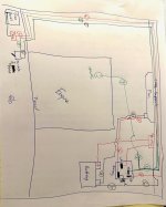
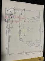
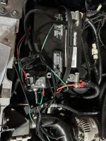
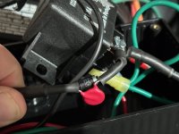
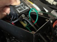
So I finally got my truck back and it's running! Well, mostly. Last time I took it out the e-fan failed to function and the truck got very hot, Fortunately, I was pulling into my garage when I noticed. Anyway, I have an old Struckby electric fan controller and fan. The fan spins freely, the battery is good and everything is connected. I've attached a diagram of the wiring, and to be honest wiring kind of scares me, its not my strong suit. I have only a very basic understanding of relays too. Can someone help explain to me how this is supposed to work and what I should be testing?

The guy who had my truck suggested grounding the wire going to the sensor and the fan should come on. It's just a single wire that slides over a post, doesn't seem very legit. I unplugged it, ran a wire from that connector to the negative battery terminal and nothing. I'm not sure if this was bad or not, but I touched wire #8 to the positive battery terminal and the fan did fire up and run.

I really want to get this figured since I cant drive the truck without a fan. And I need to determine if I have a hot restart issue or not. Plus, after soooo many years I just want to drive this darn truck again!
 

Attachments

  • IMG_3452.jpeg
    IMG_3452.jpeg
    160.4 KB · Views: 27
  • IMG_3407.jpg
    IMG_3407.jpg
    190 KB · Views: 26
Maybe someone can give you some help with how to get in touch with Struckby. I’m sure he could help you diagnose the issue. In the meantime, you can run a simple relay to turn the fan on with ignition to get you get up and running. You will want a relay and breaker that relates to the fan draw. Depending on fan size, will be between 20 and 70 amps upon start up.


Sent from my iPhone using Tapatalk
 
The current relay is 70 amps. I saw he still had a Facebook page, I messaged him almost 2 weeks ago, but no reply.

I think I have a vague understanding of how it works (all wire #'s are arbitrary):

The power side? Wire 8/9 are fused and provide the power to the fan, terminal 30. And wire #5 is the power output side of the relay, terminal 87, and is sending power to the fan. The fan is then grounded with wire #6 back to the battery. Wire #4 is somehow a ground (to the battery) even though wire #5 is providing power to the fan and is connected to the same terminal. There's also a resistor inline after the "T" right before wires #4 and #3 connect to terminal 87.

The control side? Wires # 2 and #3 complete the circuit to a 3-position toggle switch in the cab that seems to only function as an on-off switch. Additionally, power is provided by wire #7 directly from the positive battery terminal to 85. Ground on terminal 86 (or vice versa) comes off of the terminal and is then "T" with a single wire, #1, running to the sensor on the driver's side lower intake manifold, and the other, #2, running to the switch in the cab. I'm guessing when the sensor gets warm it completes a a ground, therefore completing the circuit between terminals 85 & 86, and then allowing power to flow to the fan.

I'm confused about a couple of things, why do both the switch and sensor have to be "on" (grounded?) to complete the circuit? Since they are "T"'ed before the terminal on the relay wouldn't the circuit be completed as long as one wire had a path to ground?

Second, Why does the switch have power coming from the "power" side, but ground from the "control" side? I guess if the switch is off, it would break both circuits. But, I thought that the 85/86 side and 87/30 sides would never share wiring?

Third, why would wire #4 have what appears to be a resistor and capacitor inline before connecting to the relay?
 
I still don't understand how a "T" 'ed wire would break a circuit if one of the 2 wires was still connected to power or ground?

Does anyone know how to test a relay? Or, how I can test this setup?

I found the relay on Summit, its a 75a, my bad. What is so special about it that its almost $70 for the relay alone? There are 70a fan relay kits with wiring, etc that cost less. https://www.summitracing.com/parts/...nVhViFpZY1gcHQ8zkkIBu7CoriVCCGfQaAllqEALw_wcB
 

Attachments

  • IMG_3453.jpeg
    IMG_3453.jpeg
    223.8 KB · Views: 14
  • IMG_3455.jpeg
    IMG_3455.jpeg
    130 KB · Views: 14
  • IMG_3454.jpeg
    IMG_3454.jpeg
    123.1 KB · Views: 14
The simplest & best solution is to put a mechanical fan back on a thermal clutch. It's cheaper, safer, more-reliable, less failure-prone, weighs less, and leaves more torque to go to the wheels.
 
I have an SN-95 front cover, water pump, and pulley and the truck now. Not sure if I could even bolt the stock fan back on?

How would adding a mechanical fan which will add some amount of drag to the engine increase torque output compared to the water pump spinning "freely"?
 
I have an SN-95 front cover, water pump, and pulley and the truck now. Not sure if I could even bolt the stock fan back on?

How would adding a mechanical fan which will add some amount of drag to the engine increase torque output compared to the water pump spinning "freely"?
You have to look over him. He likes oem


You need to keep the fans for blower clearance anyways
 
Nothing wrong with OEM. Not exactly my style, obviously, but to each his own.

Yep. Just have to work the bugs out, make this thing reliable and then can think about bolting on that Vortech!
 
I had the same issue with mine a few years ago. Found a bad connection at the fuse. I would just trace the power and ground from the controller back to their connections to the truck and make sure both are good.
 
I have an SN-95 front cover, water pump, and pulley and the truck now. Not sure if I could even bolt the stock fan back on?
If you can't, you can't. But nothing in your original post or signature indicates those details.
How would adding a mechanical fan which will add some amount of drag to the engine increase torque output compared to the water pump spinning "freely"?
No a thermal clutch adds no measurable "drag" to the engine when it's disengaged. When the fan is engaged, a thermal clutch takes less torque off the engine to move a given amount of air than an e-fan takes to move the same air. So a mechanical fan is more efficient, in addition to all its other benefits (cost, weight, reliability, etc.).
You have to look over him. He likes oem
This is not about the original equipment manufacturers (all the different companies that supplied parts to the assembly line); nor is it about those parts (OE). It's about simply physics, which you don't seem to understand.

And yes, I think the companies that Ford allows to put the Ford trademarks on their parts are substantially better than those NOT allowed to do so. Do you disagree? Then you should sell your Ford & buy a vehicle built by those companies. ;)
 
Nothing wrong with OEM. Not exactly my style, obviously, but to each his own.

Yep. Just have to work the bugs out, make this thing reliable and then can think about bolting on that Vortech!

Chuck, looking at your diagram I see no power feed to the fan, can you look again and reproduce the diagram? Also that is a good quality high amp relay, they cost more than the Bosch cheapo's on Amazon for foglights :)
 
TLDR: Last 6" of power wire is yellow for some reason, the wire was loose at the fuse panel.

Ha ha ha, I fixed it! I took a lot more apart than I needed to in the end, but its fixed. But I feel good about fixing it (mostly) on my own! As advised I traced the wires back to the cab, I had to unloom some sections to see where the power wire actually ran. Long story short, the power wire was run directly to the fuse panel in fuse #1, but just the bare wire was shoved in with the fuse. :rolleyes:. Tell me there's a better way? And that wire came loose. Simple as that.

What also threw me off is that a red wire runs across the bay, down the driver's fender, and into the cab BUT the last 6" is a yellow wire for some unknowable reason. So when I originally looked at the panel and didn't see a red wire I was like "ok, where the heck does that wire really go", lol.

But hey, it got me out in the garage and turned some "wrenches", and was a good learning experience. And in the end I fixed it.

Heres a correct diagram of the wiring. I think the 3 pole switch makes sense now in how it operates. Still no idea why there's a diode or resistor on the output wire, but whatever, it works. I plan to take it out tomorrow for a drive and make sure though.
 

Attachments

  • IMG_3458.jpeg
    IMG_3458.jpeg
    138.6 KB · Views: 8
...the bare wire was shoved in with the fuse. :rolleyes:. Tell me there's a better way?
Of course - several. There are fuse taps that go in with the fuse blade & provide a new spade (flat) terminal that a female on the wire will fit; there are several ways to splice the wire onto a factory wire already served by a fuse; and it's really easy to add a fuse to an empty position in the fuse block so the wire is connected just like all the factory fuse wires. Read this page:

(click this text)

...the 3 pole switch...
It has 3 terminals, but it's actually a single-pole double-throw (SPDT) switch. The relay is also SPDT (assuming it has an 87a terminal).

(click this text)

Still no idea why there's a diode or resistor on the output wire...
Your diagram doesn't show them. If you add them, or add pics showing exactly how & where they're connected (what both ends go to), I can probably tell you their purposes.
 
Heres a pic of the diode, or resistor. The relay does not have an 87a.
 

Attachments

  • IMG_3455.jpeg
    IMG_3455.jpeg
    130 KB · Views: 7
Last edited:
So all day I'm thinking about starting this truck to test the fans and drive it, but nope. Damn thing will not start at all now. I tried pedal to the floor, nothing. I connected my inline spark tester and sure enough nada, zilch, absolutely no spark coming from the distributor. I did a couple quick Google searches led me to believe it's the PIP sensor like some of you guys said in my original thread.

Do you really have to replace, or completely disassemble the distributor? Really? And there's no way to test without an oscilloscope? I called the local parts stores to see if they had an OBD1 scanner to see if I have any ignition related codes but surprise, no luck. Help. :cautious: This is frustrating after waiting 2 years and 1 month to get this truck back.

Chuck, can you hear the fuel pump come on for a couple seconds when you key the truck on?
 
Heres a pic of the diode, or resistor.
The black thing with silver markings is a diode; the round flat red thing is a capacitor. But I'd have to know what each of their leads is connected to. I can't see them inside that black tubing, or where the wiring inside goes.
Do you really have to replace, or completely disassemble the distributor?
Only if the PIP fails a published test.
And there's no way to test without an oscilloscope?
Who said that? Yes, it can be tested with a common DMM. Read this page, but you'll need a Haynes manual for the pre-'94 procedure:

(click this text)

...an OBD1 scanner...
Never use a scanner on an EEC-IV; only use a jumper wire, as Ford recommends.

(click this text)
 
I follwed your directions and got codes 15, 67, 81, 82, and 84. The computer is a 91 Mustang GT A9M. The only code that isn't expected is 15, ECU ROM failure. So the computer is just toasted?
 
Back
Top