PiMPxs AEM wideband install questions

BONESTOCK

Paid NLOC Member
I Support the NLOC
Hey all,

I've got some questions. I'm at the spot to install the wideband. I got the AEM gauge and sensor.

Here are the instructions with the AEM sensor added. I just don't understand how to install it yet. I'm not worried about preserving the factory harness so the best way to install is what I'm after.

sbanPk3.png


--------------------------------------------------------------------


S4oXuzo.png


Here's the stock O2 sensor with the wideband sensor and wiring supplied.

UIBNvSX.jpg


This bag also came with the gauge and it's own instructions. Do we use this wire? There's two connections in the back of the gauge.

v96vgDR.jpg

KRDnkRV.jpg


Here's the back of the factory O2 sensor plug. White/White/Black/Grey
0GlTdPm.jpg


Here's the back of the AEM sensor plug. Black/Grey/Yellow/Red/White
NmYMTGl.jpg

iIs7koF.jpg


I guess I can cut the factory O2 sensor plug off and solder the new sensor into the factor plug? I just don't see where the wire colors match up. This is not making sense to me. :headscratch:
 
What model AEM is that? Best I can tell the gauge IS the WB controller. If that's the case then just use the AEM harnesses to connect the O2 sensor to the gauge. Then you'll have a few wires out of the gauge. Need tto see the AEM instructions for the wire colors/pinout. Looks easy.
 
The white wire in the AEM harness (the harness that also supplies power/ground to the gauge, not the harness to the sensor) needs to go to the O2 sensor pin in the PiMP/EEC harness, which is pin 29 if I remember correctly.

You won't have any use for the stock wiring with that gauge. The OEM wiring is convenient with the Spartan since it doesn't have a integrated display like the AEM.

I used the stock O2 wiring from the computer to the battery tray to supply the signal and ground for the SSR that's running my fans.
 
Thanks guys!! I'm starting to understand!

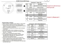
So in reference to this picture.
The red will go into keyed 12V with 5amp fuse. So just find a keyed on 12V source and add a 5amp fuse in line?
The white will go to pin 29 (heated O2 sensor input)
The black to a ground.
No use for the other wires, right?

GplJR77.jpg
 
Also if I'm not concerned with saving my harness I could just cut line on pin 29 and solder on the white wire to that, right?

Can I ground right onto the 60 pin harness too? Like splice into pin 40 or 60?

What do you all suggest I do for the red wire? Fuse box? Anything on the 60 pin harness since I'll be going through to the engine bay for the white and black wire?

https://www.nloc.net/photopost/show...rtrain-control-module-pcm-pinout-231&cat=2702
https://www.nloc.net/photopost/show...itle=eec-iv-pcm-connector-pinout-232&cat=2702
 
Oops I just saw this, the PiMP instructions have it documented, sorry I missed this earlier. Do what they say to do!

Wait.jpg
 
Yup! Reading the instructions supplied by Stinger Performance now make total sense!
I'm going to cut the wire at pin 29 and pull that through to the inside of the cab and solder on the white wire.

I'm going to combine the brown and black wire and ground that to a chassis ground at the driver side kick panel area.

The red wire I'll tee into a 12V keyed on source.
 
Don’t combine brown and black you’ll end up with a voltage offset, wire them just like they say those are actually two different grounds.
 
Don’t combine brown and black you’ll end up with a voltage offset, wire them just like they say those are actually two different grounds.

Ok. I was saying that because it mentions that in the 89-95 Speed density section that the signal ground can go to the heater ground (pin 40-60) as well.

And I figured pin 40/60 is the same as a chassis ground like the kick panel area.
 
Just use a fuse tap on a KO fuse. Easy-peasy.

Also, solder isn't the best idea because it's brittle and will strain/break easily. Use a good, shrink-and-adhesive weatherproof crimp connector.

I spent a lot of time redoing all the solder joints in my wiring harness with good crimps. Recently had a solder joint that I'd forgotten about making things freaky in my taillights.

Thanks for the tip! Will do. IT did come with the crimps so I'll use those.
 
Don’t combine brown and black you’ll end up with a voltage offset, wire them just like they say those are actually two different grounds.
I did this and it cost me a controller.

Sent from my SM-G991U using Tapatalk
 
Just use a fuse tap on a KO fuse. Easy-peasy.

Also, solder isn't the best idea because it's brittle and will strain/break easily. Use a good, shrink-and-adhesive weatherproof crimp connector.

I spent a lot of time redoing all the solder joints in my wiring harness with good crimps. Recently had a solder joint that I'd forgotten about making things freaky in my taillights.
They don't use solder in high end race cars. Everything is crimped, wound and sealed. Vibration kills solder.

Sent from my SM-G991U using Tapatalk
 
Back
Top