aseecobra
Member
Hey guys,
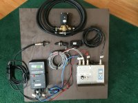
Just wanted to share something I designed and constructed this semester as a requirement of an engineering degree I'm finishing up.
I have a 10lb vortech on my stock motor with 19lb injectors, non spring assist 12:1 fmu and GSL392 pump. The mechanical fmu was lean on the low end as it should be being a non spring assist and would go rich at higher boost approaching 10psig. The goal of the electronic fmu is to hold a flat AFR set point across all levels of boost.
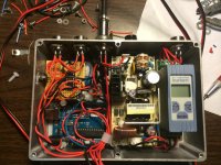
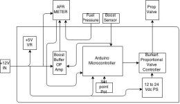
The heart of the electronic controller is an Arduino Uno mircrocontroller running a PID closed loop control program. In the short amount of time I had left to tune the system, the results showed merit for further tuning.
A target AFR set point is established using a front panel control. An Innovate LM-1 wideband is used for the process feedback. A proportional flow valve is used for the process control. The LM-1 was also used for data logging.
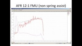
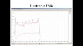
As you can see in the graphs, both the mechanical and electronic fmu have a noticeable lean spike. Its there without the blower too. Its a result of the factory SD accelerator enrichment rate. However instead of the AFR being on the lean side at low boost with the mechanical fmu, its now a little too rich with the electronic. This is where more tuning efforts are required.
Red = fuel pressure
Black = boost
Purple = AFR
Thanks for looking.
Just wanted to share something I designed and constructed this semester as a requirement of an engineering degree I'm finishing up.
I have a 10lb vortech on my stock motor with 19lb injectors, non spring assist 12:1 fmu and GSL392 pump. The mechanical fmu was lean on the low end as it should be being a non spring assist and would go rich at higher boost approaching 10psig. The goal of the electronic fmu is to hold a flat AFR set point across all levels of boost.
The heart of the electronic controller is an Arduino Uno mircrocontroller running a PID closed loop control program. In the short amount of time I had left to tune the system, the results showed merit for further tuning.
A target AFR set point is established using a front panel control. An Innovate LM-1 wideband is used for the process feedback. A proportional flow valve is used for the process control. The LM-1 was also used for data logging.
As you can see in the graphs, both the mechanical and electronic fmu have a noticeable lean spike. Its there without the blower too. Its a result of the factory SD accelerator enrichment rate. However instead of the AFR being on the lean side at low boost with the mechanical fmu, its now a little too rich with the electronic. This is where more tuning efforts are required.
Red = fuel pressure
Black = boost
Purple = AFR
Thanks for looking.